¶ ZTurn and Active Test Board
¶ Powering Scheme
By default, the ZTurn receives power from both the mini-USB UART and the active board power supply.
This can cause several problems:
- Over-loading the power available from the USB hub
- Inability to remotely power cycle the ZTurn7020 when connected to the USB-UART
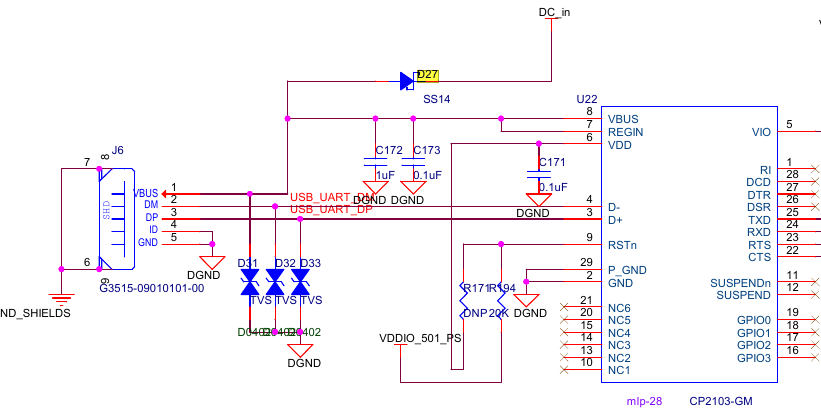
The recommendation is to remove the D27 diode, located close to the UART port. This disables powering from USB.
The ZTurn can also get power from the powersupplies through the USB hub. If the powersupplies are plugged in at boot, it can cause the ZTurn/Active Board to enter a state in which the HV off current is read to be higher than it is (not yet clear why). Removing the D12 diode fixes this issue.
¶ IO Bank Power
The ZTurn ties the VCCIO pins to 3.3V via an inductor. This allows the different on-board toys to be powered without the need for an external power supply. However this prevents the ZTurn to use the Zynq differential pairs in LVDS25 mode. The LVDS25 mode requires 2.5V, which is provided via the Active Board.
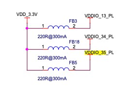
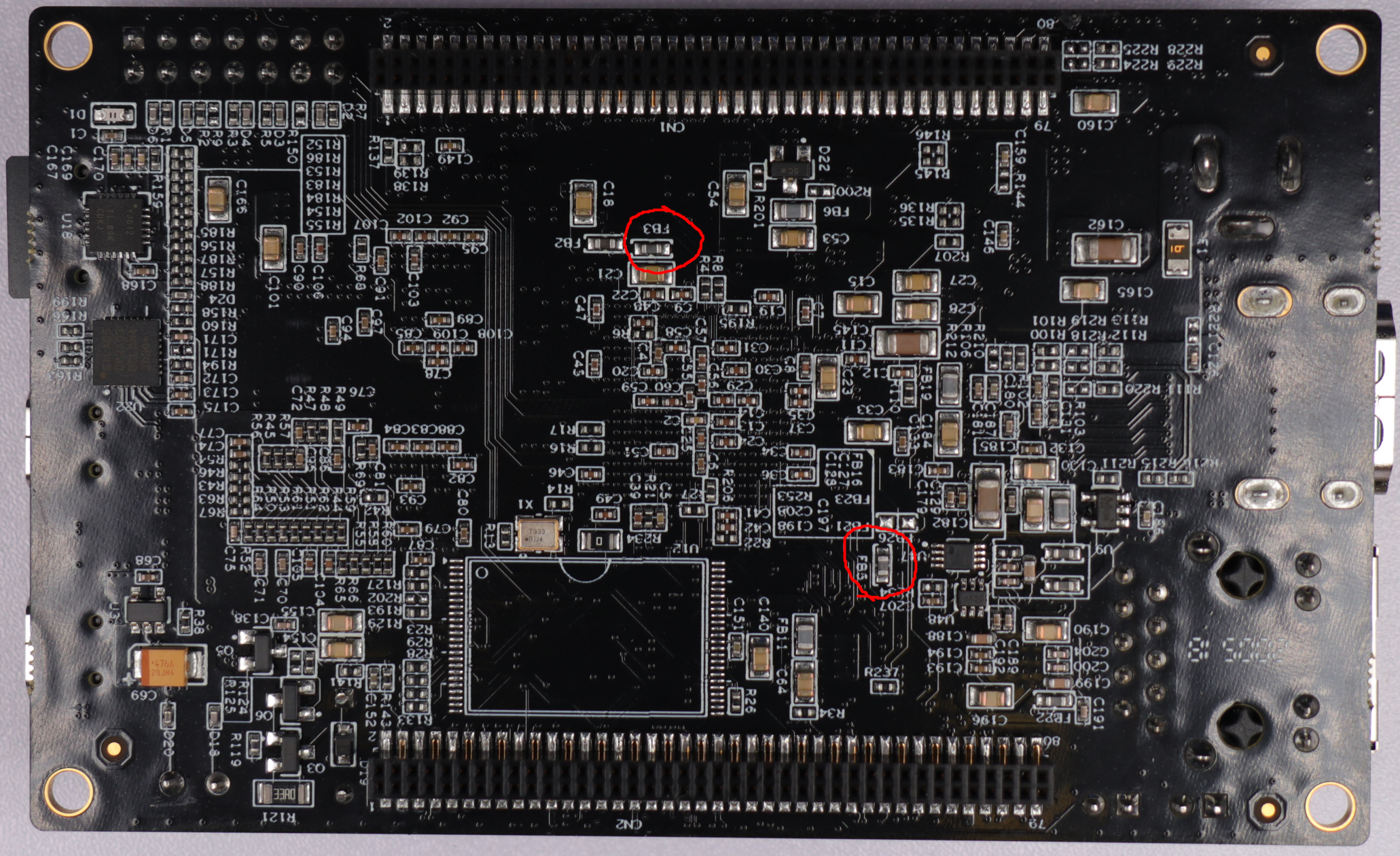
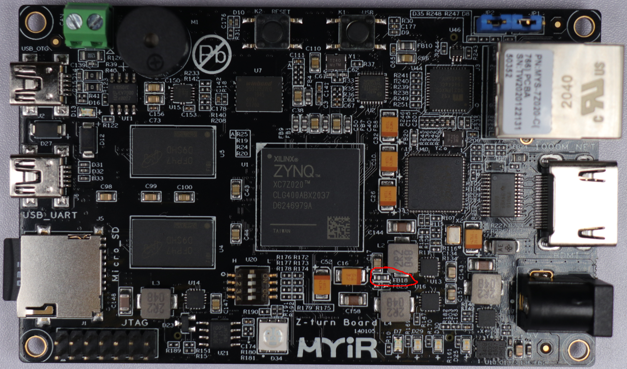
The inductors FB3, FB5 and FB18 need to be removed. Their location is shown in the images below. The removed chips should be put in the little container keeping track of them.
¶ USB OTG Interfering w/ HV Current Measurement
The ZTurn can get power from the Prologix GPIB cards via USB. If the USB is connected to the GPIB card boot, it can cause the ZTurn/Active Board to enter a state in which the HV off current is read to be higher than it is (~240μA). The mechanism behind this is not yet clear. Removing the D12 diode fixes this issue.
