¶ Table of contents
¶ Setup Instructions
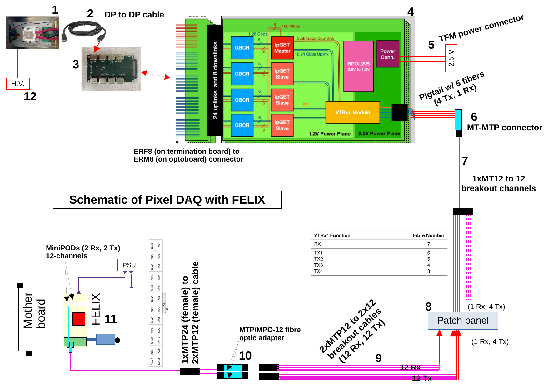
These instructions detail how to build a FELIX test setup starting from the front-end electronics leading to the FELIX board. More details on each of the parts used in the setup are listed below, and a parts list is provided at the end of this document.
¶ Setting up Front-End and Adapter Card
Connect the front-end electronics (such as a SCC or quad module) to an adapter board with a DP to DP cable. Schematics for several adapter boards are shown below (e.g. Zaza board). For simplicity of mapping connections it is recommended for an initial setup to choose a port that maps to TX line 0 and RX line 0 (e.g. for a Zaza board, the second port). The adapter card connects directly to the optoboard via the ERF8-ERM8 connector.
¶ Powering the Optoboard
Different optoboards have different requirements for power depending on whether or not they have an oboard BPOL converter. If they have a BPOL converter, only one input voltage needs to be applied. If the optoboard has no onboard BPOL, two voltages will need to be applied. More detailed information about the optoboard setup and required voltages can be found here: Optoboard Hardware Documentation. For an v4 optoboard with an onboard BPOL, a single 2.5 V source (max. recommended current 1A) should be supplied. A TFM power connecter is used to power the optoboard and may need to be custom-built by the user depending on the powering needs.
¶ Patch Panel Connections
Connect an MT-MTP connector to the end of the fiber cable on the optoboard. Attach a 1xMT12 to 12 breakout channel optical cable to the other end of the connector. These cables should be connected to a patch panel paying particular attention to fiber ordering for correct TX and RX mapping. The precise mapping will depend on the setup and which adapters are used as some switch polarity - some example setups include (depending on the key polarity of adapters):
 |
 |
|---|---|
| Example fiber mapping (1) | Example fiber mapping (2) |
¶ FELIX Connection
For each of the MTP12 to 12 breakout optical cables on the FELIX-side, attach a MTP/MPO-12 fiber optic adapter to one end, and connect both to a MTP24 adapter as shown in the schematic below. Connect the other end of this cable to the FELIX card. The fiber mapping for the FELIX MiniPODs is shown below in the hardware list.
¶ Testing and Helpful Links
Once the setup is connected, the FELIX firmware, software, and driver need to be set up, as well as the Optoboard communication method and YARR. Information about how to carry out these steps can be found at the following pages:
¶ DAQ setup
¶ Schematic
¶ New 6-DP Zaza adapter board
Schematic:
https://github.com/zazachubin/RD53B_Quad_6DP_to_ERF8_Data_Adapter/blob/master/Docs/RD53B_Quad_6DP_to_ERF8_Data_Adapter.pdf
Project:
https://github.com/zazachubin/RD53B_Quad_6DP_to_ERF8_Data_Adapter/tree/master
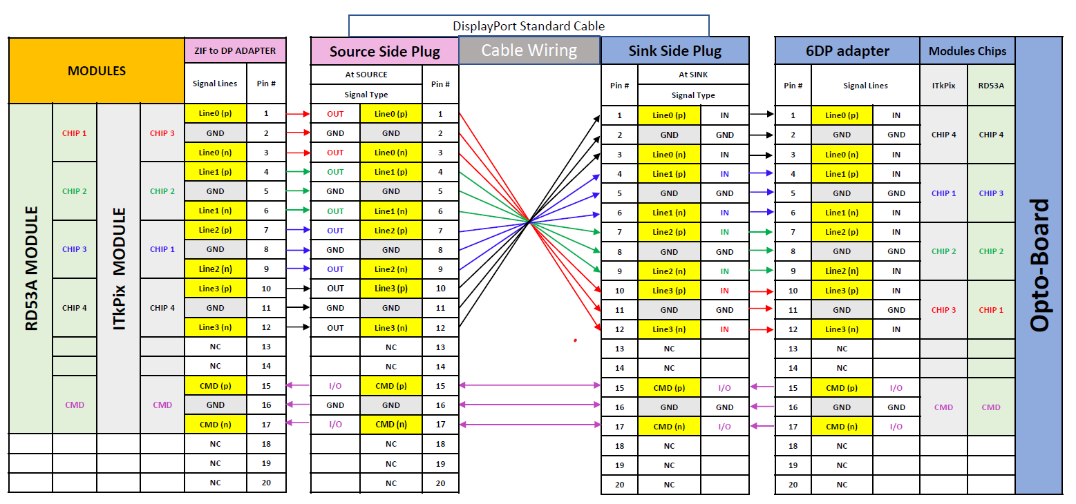
You should take in account mapping of the display cable, between
ZIF-DP-adapter to 6DP-adapter:
Also here is 6DP-adapter users mapping for FELIX:
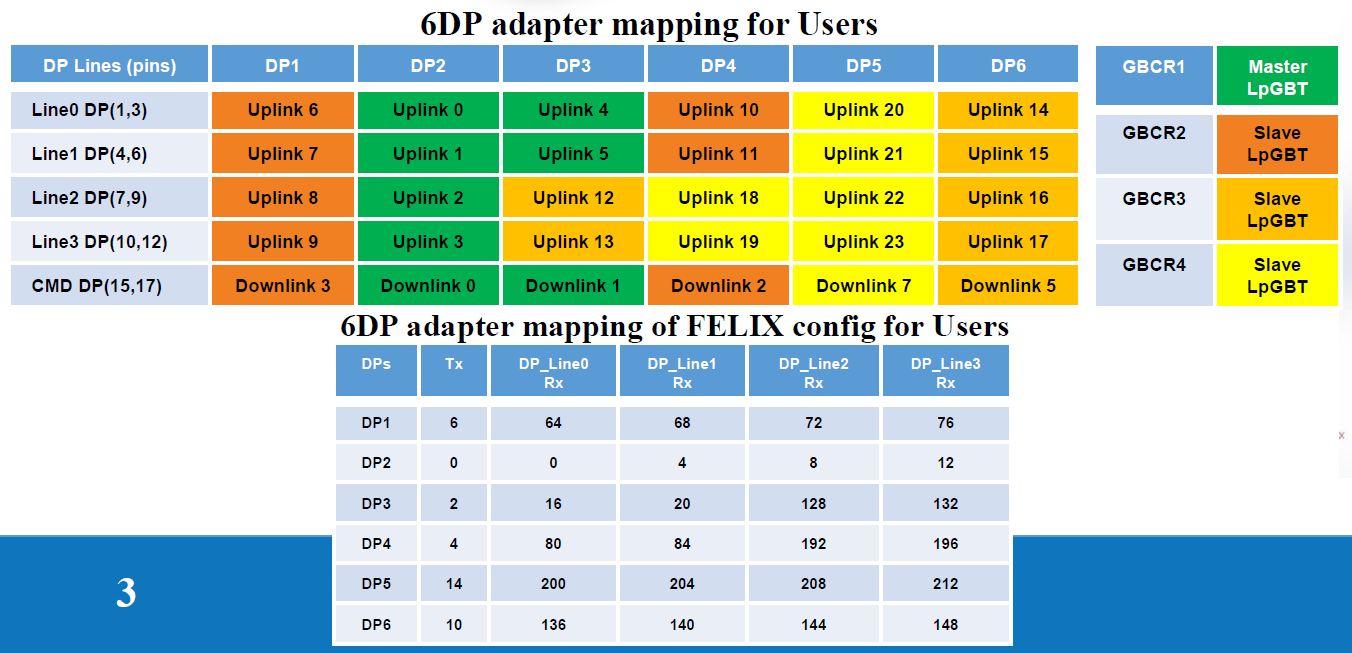
Optoboard uplinks and downlinks configuration:
Rx inversion Tx default for ITkPix module
Rx default Tx default for RD53A module
An example optoboard configuration for ITkPix module can be found here.
¶ Parts List
A summary of the parts needed for putting together a FELIX testing setup is provided in the following table. More information including images and diagrams of the different parts is included in the next section.
| Part | Quantity | Description |
|---|---|---|
| DP-DP cable | 1 | Connect from front-end to adapter card |
| Adapter Card | 1 | (e.g. Zaza board) Connects to optoboard via ERF8-ERM8 connecter |
| MT-MTP Adapter | 1 | Connects single optical fiber leaving optoboard to patch panel: Adapter Fiber Optic Connector MPO Receptacle To MPO Receptacle Panel Mount, Flange (2 Hole) |
| Power Cable for Optoboard | 1 | TFM power connector |
| MT12 to 12 LC Cable | 1 | Goes from MT-MTP Adapter to patch panel: Customized 8-144 Fibers Senko MPO-12 OM4 Multimode Elite Breakout Cable, Fibers count = 12 (1x12F) |
| Patch Panel | 1 | FHD Fiber Adapter Panel, 24 Fibers OM4 Multimode, 12 x LC UPC Duplex (Aqua) Adapter, Ceramic Sleeve |
| MTP 12 to 12 LC Cable | 2 | 12 RX and 12 TX on FELIX-side of patch panel: Customized 8-144 Fibers Senko MPO-12 OM4 Multimode Elite Breakout Cable, Fibers count = 24 (2x12F) |
| MTP-MTP Connector | 2 | First option: Coupler Fiber Optic Connector MPO Receptacle To MPO Receptacle Panel Mount, Flange, Snap-In, Second: US Conec MTP®/MPO-8/12/24 Grey Fiber Optic Adapter/Coupler without Flange, Key Up to Up |
| 24 Fiber MTP to dual MTP | 1 | Combines the two MTP cables from the patch panel into one to attach to FELIX: MTP to dual MTP |
| JTAG Programming Cable | 1 | For programming FELIX firmware |
¶ Hardware components
1. RD53B Pixel Quad module

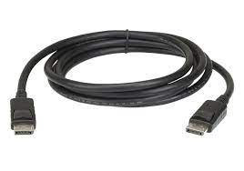
2. Display port to display port cable
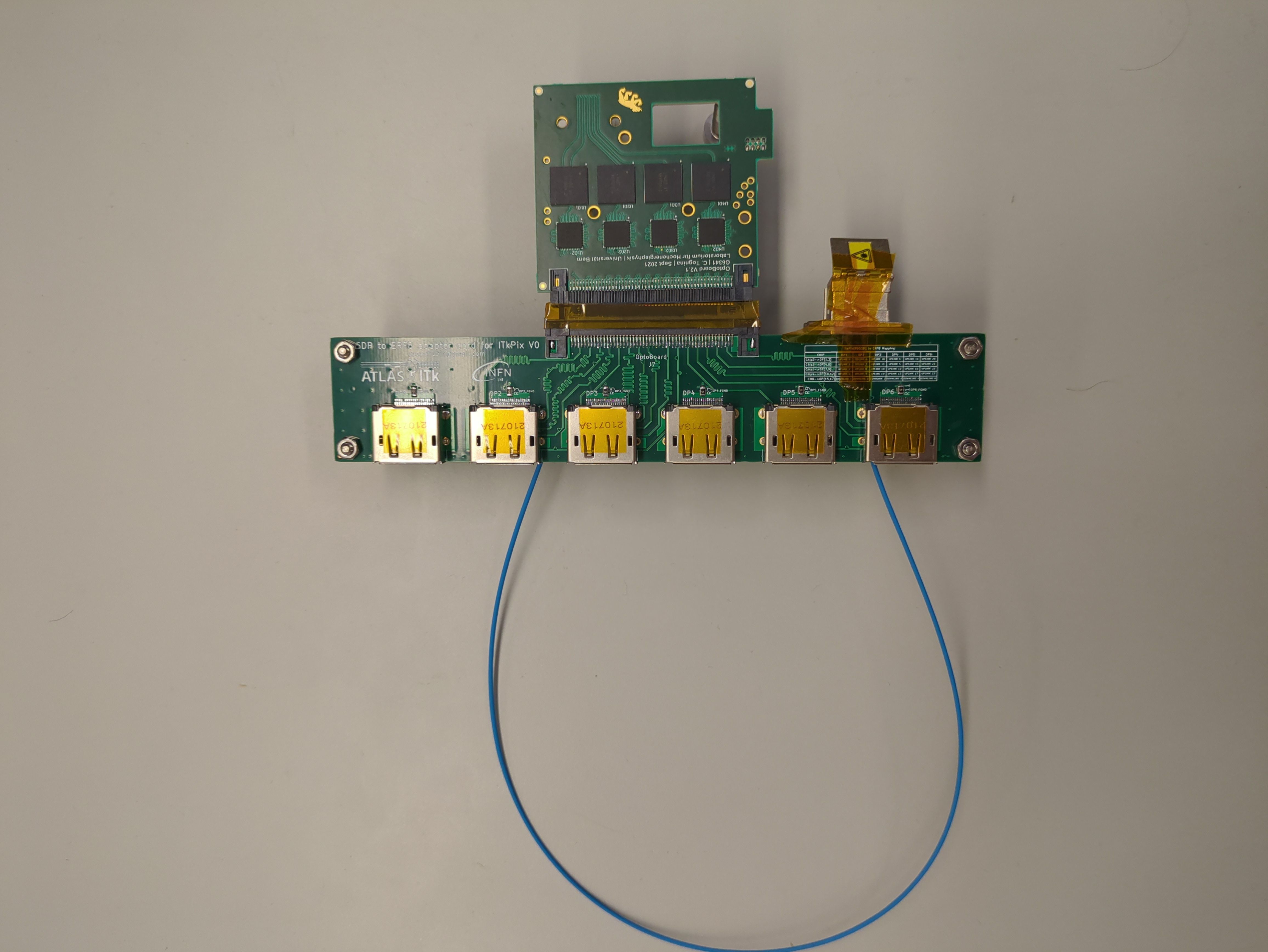
3. Adapter board
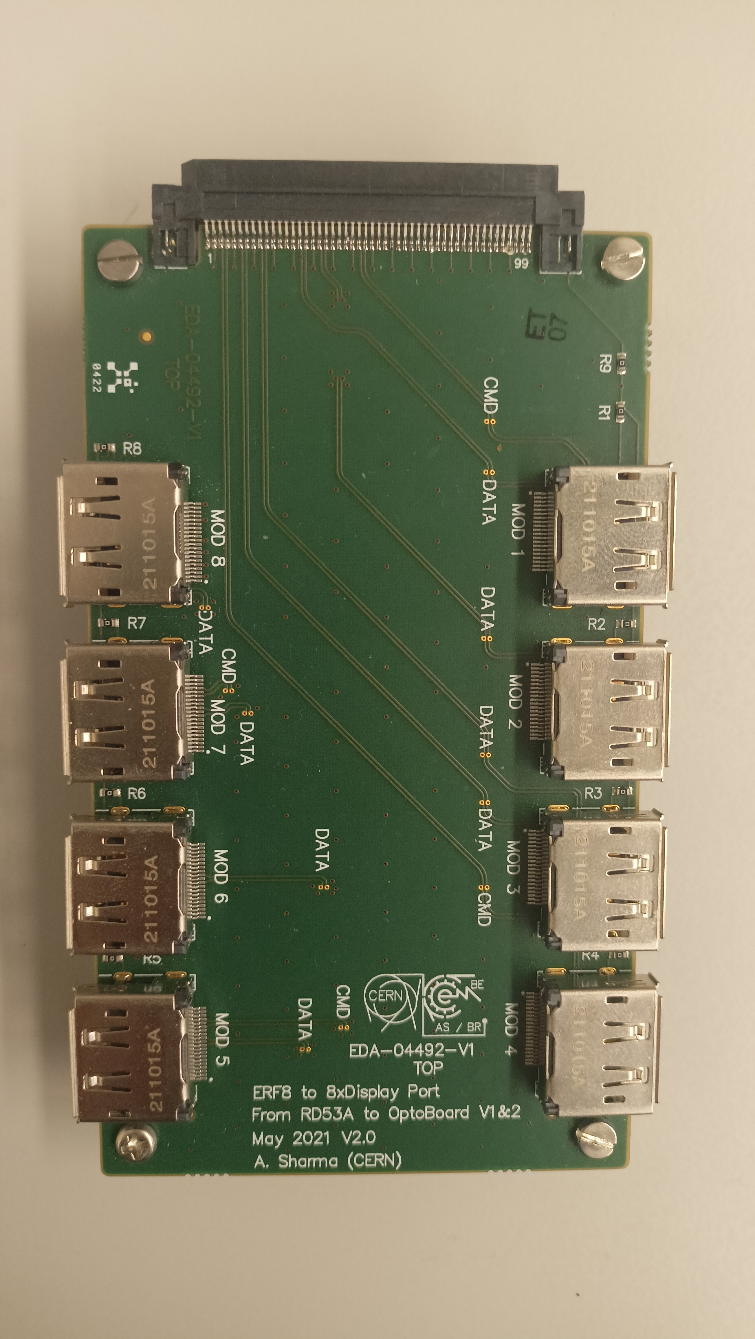
Resources:
ERF 8xDP adapter channel routing (https://gitlab.cern.ch/bat/optoboard_felix/-/wikis/ERF-8xDP-adapter-channel-routing)
ERF 8xDisplayPortV2 schematics (https://gitlab.cern.ch/itk-pixel-electronics/services/optosystem/-/blob/master/ERF-8xDisplayPort/ERF-8xDisplayPortV2_schematics.pdf)
4. Optoboard
An actual optoboard, from the front and the back side, are shown here:

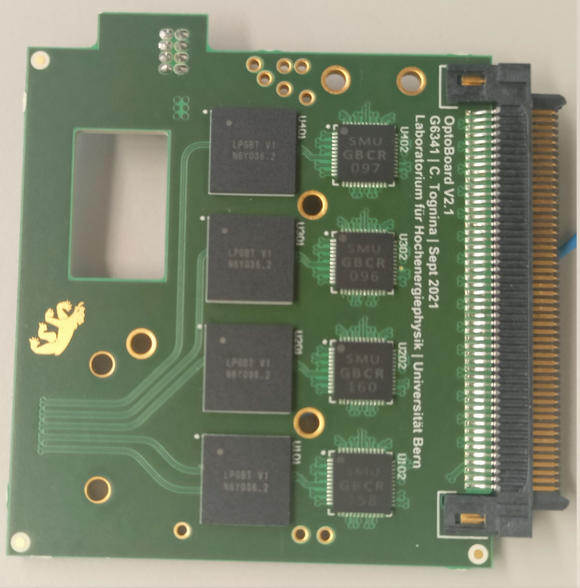
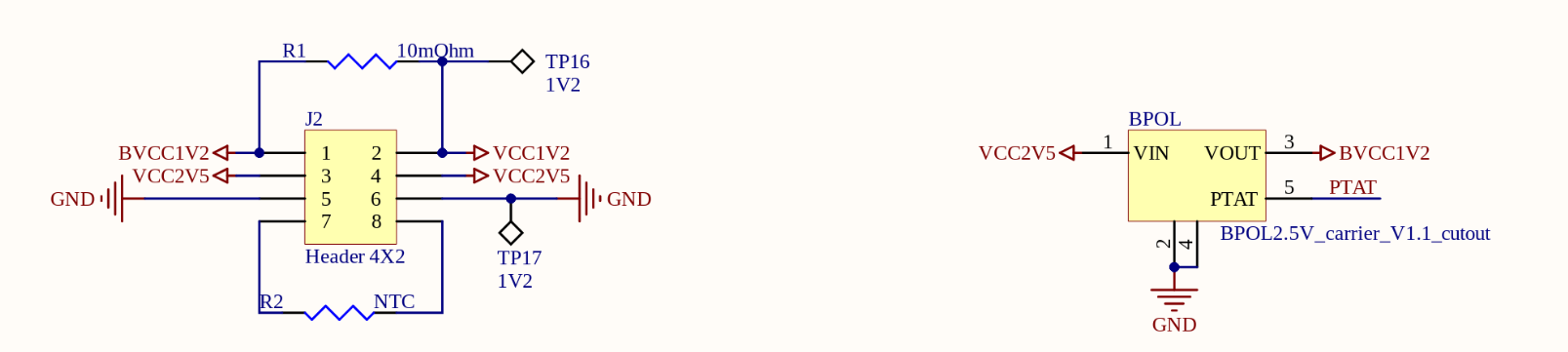
The rectangular hole on the board is the missing bPOL2V5 DC/DC convertor. So this means that we need to supply the 1.2 V also to the board, in addition to 2.5 V supply, directly from outside. The pinout schematics for the power connector and the LpGBT powering scheme (with 1.2 V supply) can be found here - https://gitlab.cern.ch/itk-pixel-electronics/services/optosystem/-/blob/master/G6341_OptoBoard_V2_1/OptoBoard_V2_1_Schematic Prints.PDF
The pin definition for GBCR (also requires 1.2 V) can be found here - https://edms.cern.ch/ui/file/2384089/2.1/GBCR2_user_manual_v2.1.pdf
The ERM8 connector pinout on the optoboard is shown below:
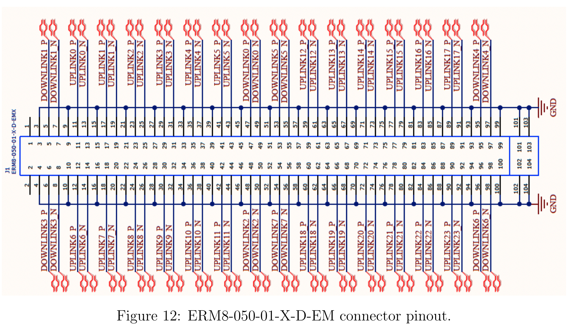
Credit: https://edms.cern.ch/ui/file/2379183/1/AT2_IP_MG_0010_v2.5.pdf
VTRx+ module pigtail to MTP12 optical interface specifications:

Credit: https://edms.cern.ch/ui/file/1719329/1/VTRxPlus_spec_v2.6.pdf
Note:
For the LBL setup, we set (1.25V, 3A) for channel 1 and (2.5V, 0.5A) for channel 2 from power supply.
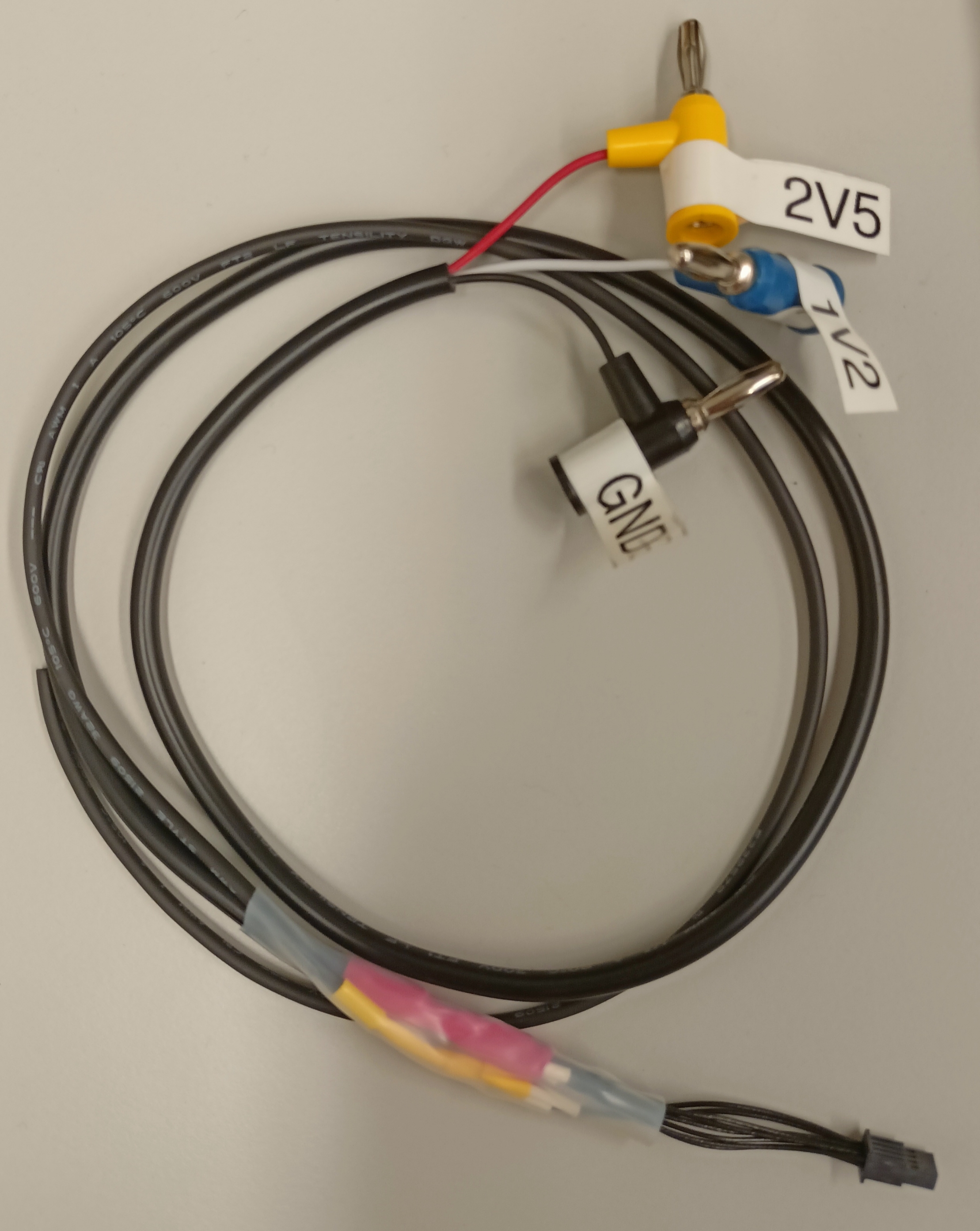
5. TFM power connector
The power connector has 8-pins and the pinout definition is shown in the image below.
The image of the actual power cable crafted in accordance with the appropriate connections is shown below.
6. MT-MTP connector
Product description:
Adapter Fiber Optic Connector MPO Receptacle To MPO Receptacle Panel Mount, Flange (2 Hole)
(https://www.digikey.com/en/products/detail/molex/1061141100/2421498)
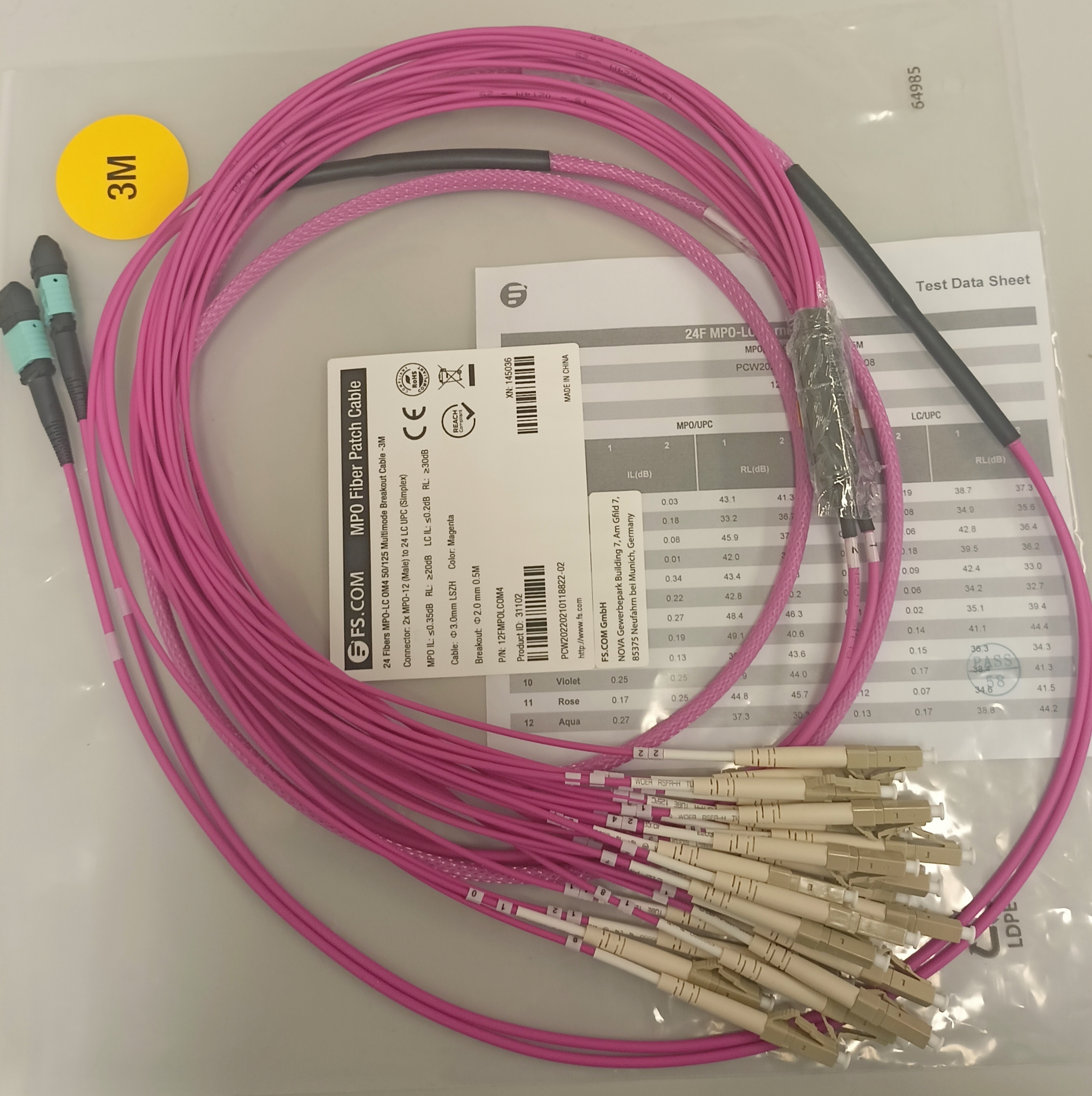
7. 1xMT12 to 12 LC cable
Product description:
Customized 8-144 Fibers Senko MPO-12 OM4 Multimode Elite Breakout Cable, Fibers count = 12 (1x12F)
(https://www.fs.com/products/31102.html)
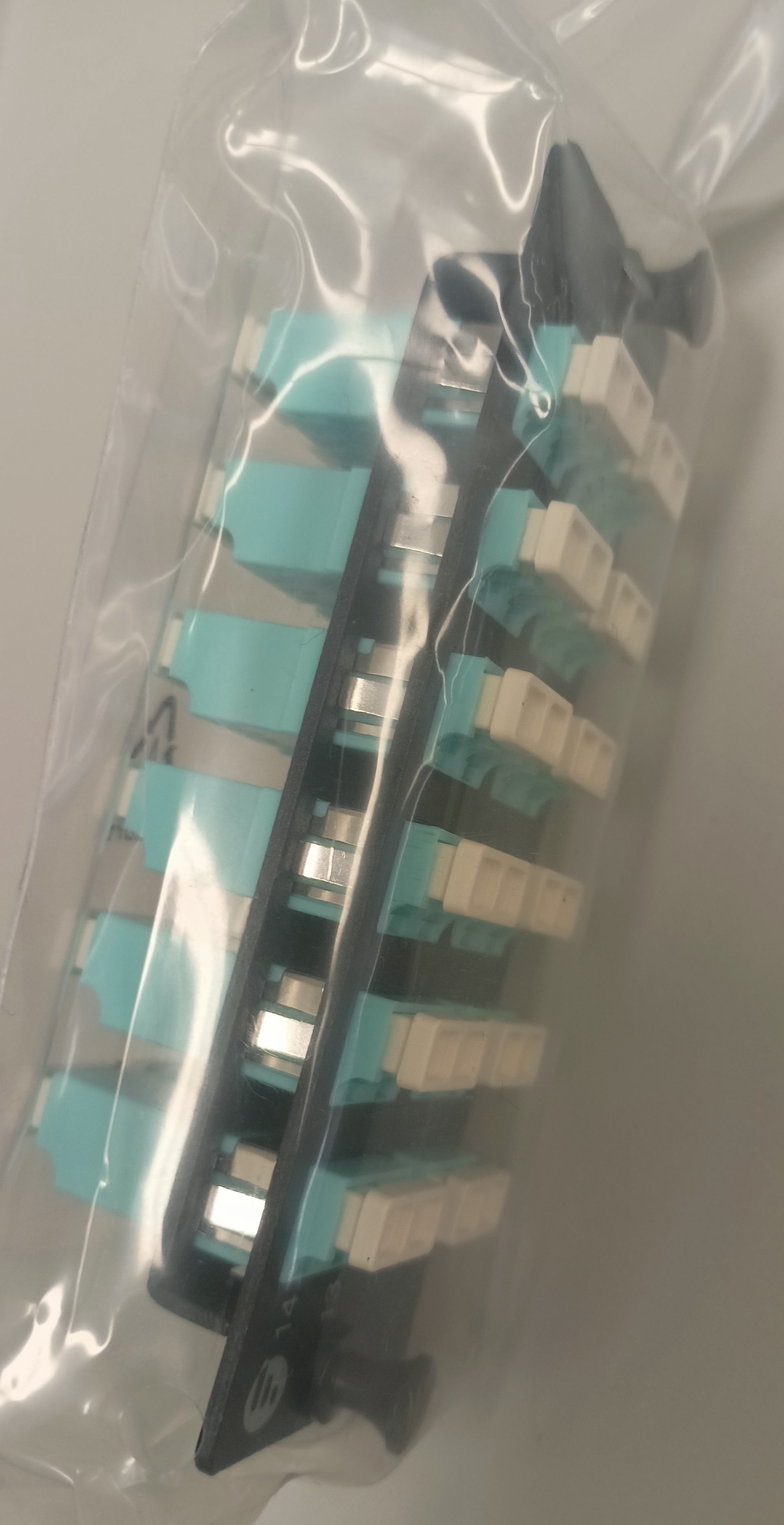
8. Patch panel
Product description:
FHD Fiber Adapter Panel, 24 Fibers OM4 Multimode, 12 x LC UPC Duplex (Aqua) Adapter, Ceramic Sleeve
(https://www.fs.com/products/41998.html?attribute=4471&id=199443)
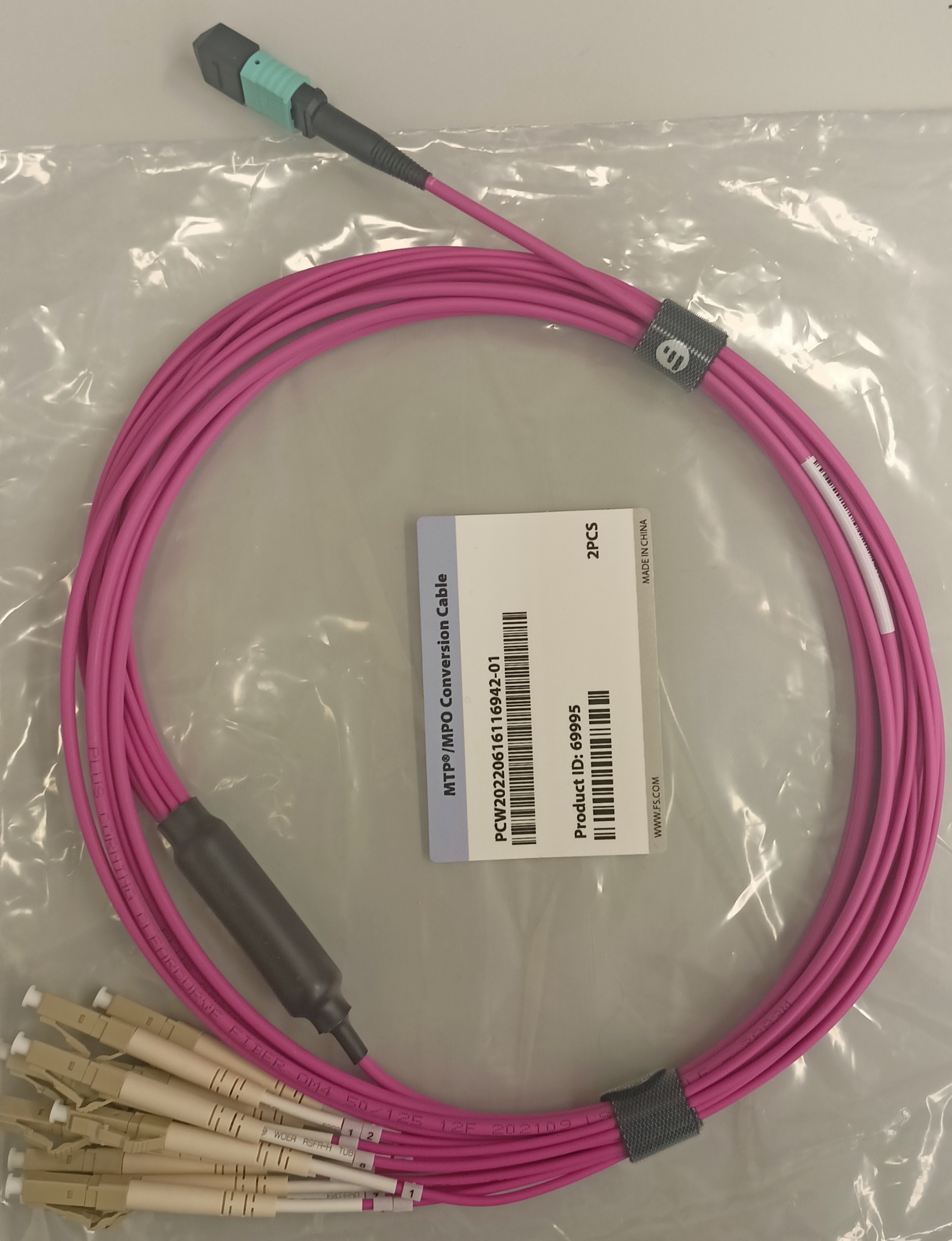
9. 2xMTP12 to 2x12 LC (12 Rx, 12 Tx)
Product description:
Customized 8-144 Fibers Senko MPO-12 OM4 Multimode Elite Breakout Cable, Fibers count = 24 (2x12F)
(https://www.fs.com/products/31102.html)
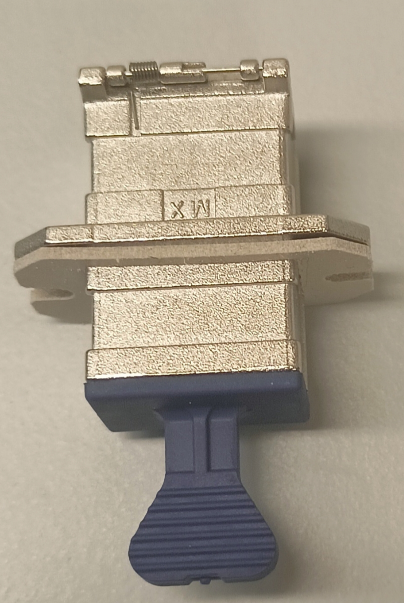
10. MTP-MTP connector
Product(s) description:
- Coupler Fiber Optic Connector MPO Receptacle To MPO Receptacle Panel Mount, Flange, Snap-In
(https://www.digikey.com/en/products/detail/adam-tech/OPMG1BNNC1PC/13586881) - US Conec MTP®/MPO-8/12/24 Grey Fiber Optic Adapter/Coupler without Flange, Key Up to Up
(https://www.fs.com/products/12072.html)

11. FELIX board
Product description:
FLX-712 (BNL-711 V2) board
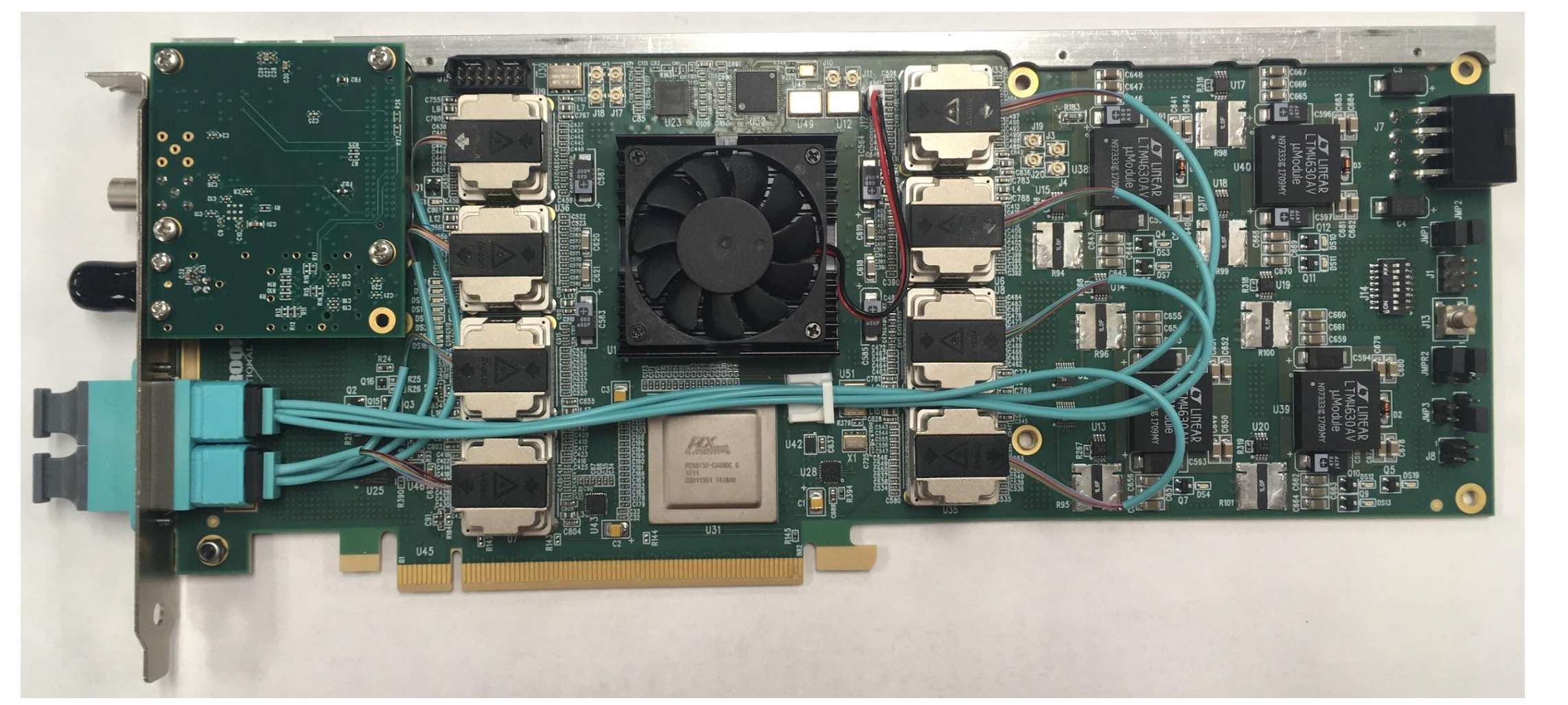
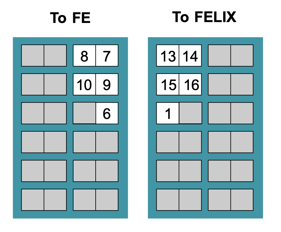
The FELIX card hosts 4 MiniPOD transmitters and 4 MiniPOD receivers, as seen above. Each MiniPOD has 12 channels. The FELIX board at LBNL is a slight modification of the above board with only 4 MiniPODs instead of 8 MiniPODs. Hence, instead of 48-channel configuration, we have 24-channel configuration always. The fibre mapping of the two MiniPODs to the MTP24 couplers in the 24-channel configuration is shown below:

Whereas, for a 48-channel connfiguration i.e. with 8 MiniPODs, a MTP48 coupler is used. The corresponding fibre mapping of the MiniPODs connected to the MTP48 coupler is shown below:

The pin assignment for 24-channels configuration with 4 MiniPODs, looking from the FELIX-side, is shown below:

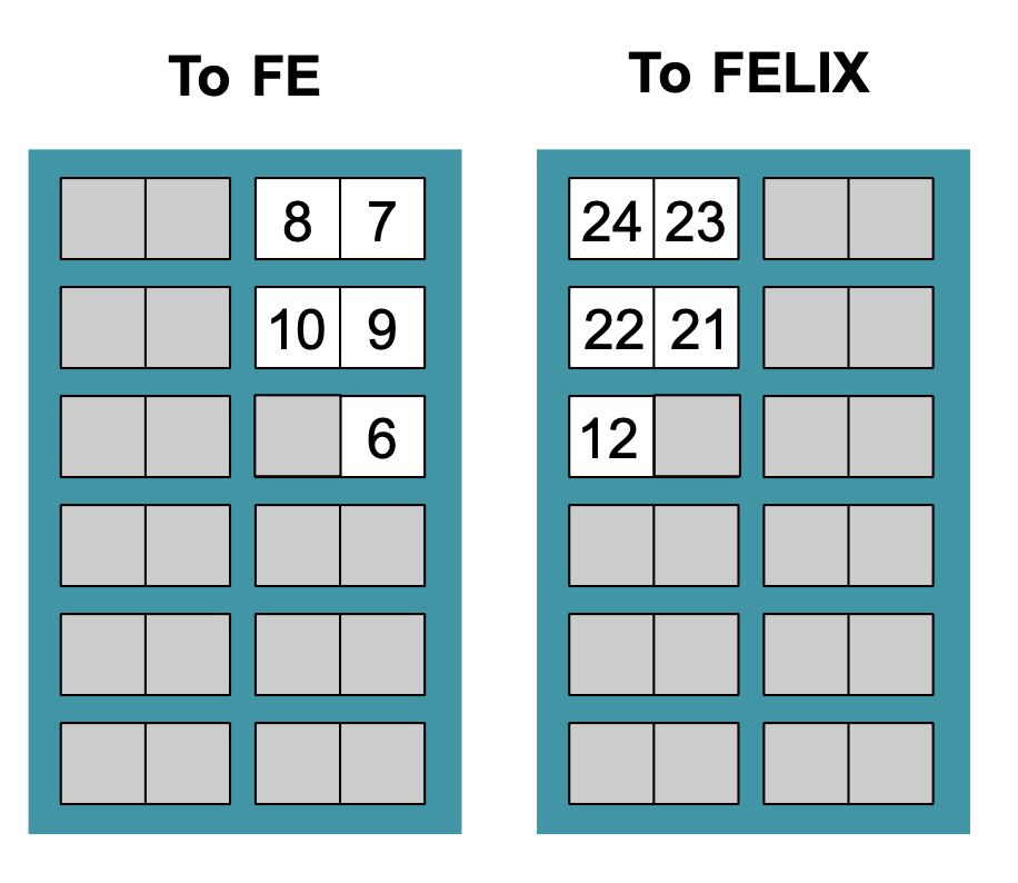
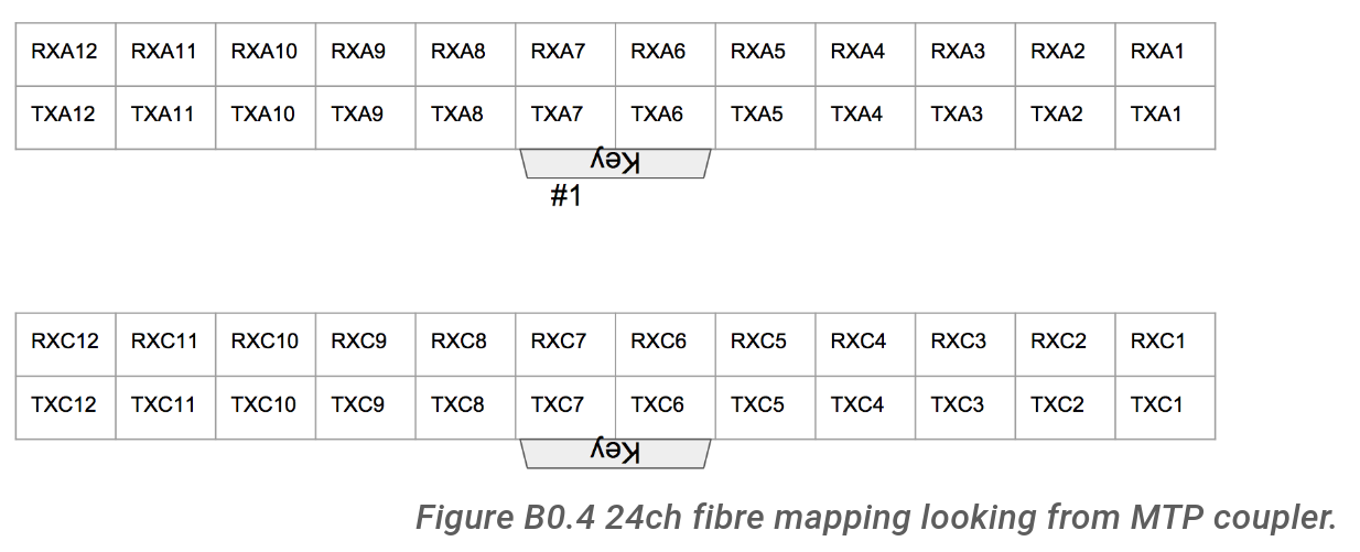
The pin assignment for 24-channels configuration with 4 MiniPODs, looking from the MTP24 coupler-side, is shown below:
Similarly, the pin assignment for the 48-channel configuration, from both sides, can be seen in Figures B0.5 and B0.6 in the above hyperlink.
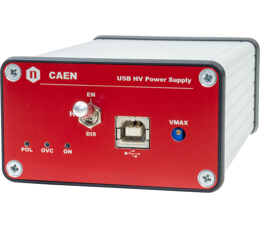
12. C.A.E.N. High Voltage supply